
The LM741 is the electronic equivalent of a classic car with no airbags, no Bluetooth, questionable brakes, and a fan club that insists it still “builds character.” It is legendary, widely available, cheap, and historically important. It is also one of the most misunderstood operational amplifiers ever dropped into a breadboard by hopeful beginners.
To be fair, the LM741 does not suck because it is badly made. It sucks because people keep asking it to do modern op-amp jobs it was never designed to do. It came from an era when dual power supplies were normal, 5V microcontrollers were not running the world, and “rail-to-rail” sounded more like a train schedule than an op-amp feature. The chip became famous because it was stable, rugged, educational, and easy to use compared with earlier analog ICs. But in today’s circuits, especially single-supply sensor interfaces, battery-powered projects, audio experiments, Arduino builds, and precision measurement systems, the LM741 often behaves like a grumpy museum exhibit with eight pins.
This article explains why the LM741 sucks in practical terms: not as internet drama, but as useful engineering reality. We will look at its power supply requirements, input limitations, output swing problems, offset errors, bias current, speed, noise, and why it is still somehow immortal.
The LM741 Is OldAnd That Matters
The original 741-style op amp dates back to the late 1960s. That alone does not make it bad. A hammer is old too, and nobody complains when it hammers. The problem is that op amps are not hammers. They are precision analog building blocks, and the world around them has changed dramatically.
Modern electronics often run from 3.3V or 5V supplies. Sensors may produce tiny signals close to ground. Microcontrollers expect clean, predictable voltage levels. Portable products care about battery life. Audio circuits care about distortion and noise. Precision circuits care about offset, drift, and input current. The LM741 was not born for that party. It wants generous supply voltage, plenty of headroom, modest frequency demands, and a designer who reads the datasheet before lighting the breadboard incense.
The LM741’s typical gain-bandwidth product is around 1 MHz, its slew rate is about 0.5 V/µs, it is not rail-to-rail, and its input bias current can be large compared with modern CMOS or JFET-input amplifiers. Those numbers are not automatically fatal, but they are warning labels. Ignore them and the circuit will not politely fail. It will produce a weird voltage, clip early, oscillate, distort, saturate, or simply stare at you from the breadboard like you owe it an apology.
Problem #1: The LM741 Hates Low-Voltage Single-Supply Circuits
The most common beginner mistake is powering an LM741 from a single 5V supply and expecting it to behave like a modern rail-to-rail op amp. It will not. The LM741 typically needs a much larger supply range than tiny modern circuits provide. It was commonly used with dual supplies such as ±12V or ±15V, where the signal can sit comfortably around ground and the op amp has breathing room above and below the waveform.
On a single 5V supply, the LM741 is basically trapped in a shoebox. Its inputs cannot properly sense voltages close to either supply rail, and its output cannot swing all the way to ground or all the way to the positive rail. So if you feed it a sensor signal near 0V, it may be outside the valid input common-mode range. If you expect a 0V to 5V output, congratulations, you have built a disappointment generator.
Example: The 5V Microcontroller Mistake
Imagine you have a sensor producing 0.2V to 2.0V, and you want to amplify it for an Arduino-style analog input. You grab an LM741 because it is famous and the package looks friendly. You power it from 5V and ground. The math says your non-inverting amplifier should produce a nice scaled signal. The real circuit says, “Absolutely not.”
Why? Because the input voltage may be too close to the negative rail, the output cannot reach the rails, and the amplifier may saturate or respond unpredictably. The equations for ideal op amps are not broken. Your assumption that the LM741 is ideal is broken. Big difference.
Problem #2: It Is Not Rail-to-Rail
Rail-to-rail input/output op amps are designed to work close to their supply rails. The LM741 is not one of them. That means both the input and output need headroom. In plain English, the LM741 does not like signals near the top or bottom of its power supply range.
This matters because modern circuits often live near the rails. A temperature sensor may output a voltage close to ground. A photodiode circuit may need to process very small signals. A microcontroller ADC may expect the full 0V to 3.3V range. The LM741 shrugs at these expectations. It comes from the land of dual supplies, where ground sits in the middle and the chip has lots of room to swing.
Even when the LM741 technically “works,” the usable range may be much smaller than the supply voltage suggests. A beginner sees 0V and 12V rails and thinks the output can go from 0V to 12V. The LM741 sees those rails and thinks, “How about something less convenient?”
Problem #3: The Slew Rate Is Slow
Slew rate describes how fast an op amp’s output voltage can change. The LM741’s typical slew rate is about 0.5 V/µs. That may sound fast if you are thinking in human terms, but electrons are not impressed.
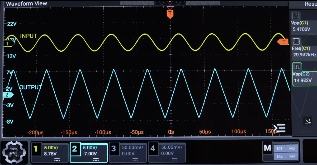
For slow DC circuits, this may not matter. For audio, square waves, pulse signals, filters, function generators, or anything with fast edges, it matters a lot. If the output needs to move faster than the op amp can manage, the waveform becomes distorted. A sine wave may start looking tired. A square wave may turn into a ramp. Your “clean signal” becomes analog soup.
Example: Audio Distortion
Suppose you want a 10V peak-to-peak audio signal at higher frequencies. The required output slope increases with frequency and amplitude. With only 0.5 V/µs of slew rate, the LM741 can run out of speed surprisingly quickly. When that happens, it is not a subtle audiophile problem involving golden ears and expensive cables. It is actual waveform distortion.
For modern audio, better choices exist. Devices like the NE5532, TL072, OPA2134, or other audio-focused op amps offer better noise, speed, input characteristics, and distortion performance depending on the circuit. The LM741 can make sound, yes. So can a kazoo. That does not make it the right tool for the recording studio.
Problem #4: The Gain-Bandwidth Product Is Limited
The LM741’s gain-bandwidth product is around 1 MHz. That means gain and frequency trade against each other. If you configure the op amp for a gain of 100, the available bandwidth is greatly reduced. If you need high gain and useful frequency response at the same time, the LM741 begins sweating through its tiny plastic package.
This is one reason beginner circuits behave beautifully in theory and badly on the bench. The ideal op amp in the textbook has infinite bandwidth. The LM741 does not. The simulator may be using a simplified model. The real chip has internal compensation, phase limitations, parasitic effects, and a speed limit that was not negotiated with your project deadline.
Problem #5: Input Bias Current Can Create Real Errors
An ideal op amp input draws no current. Real op amps draw some input current. In bipolar-input devices like the LM741, that current can be large enough to matter, especially with high-value resistors or high-impedance sensors.
Input bias current flowing through resistance creates voltage error. For example, if an input bias current flows through a large resistor, Ohm’s law quietly adds an unwanted voltage. The op amp then amplifies that error as if it were part of the signal. This is the kind of bug that makes people blame the sensor, the breadboard, the moon phase, and finally the op amp.
Modern CMOS and JFET-input op amps often have dramatically lower input bias currents. That makes them better for sensor interfaces, photodiode circuits, pH probes, sample-and-hold circuits, and other high-impedance applications. The LM741 is not impossible to use here, but it makes you do extra work for no good reason. That is not charming. That is analog paperwork.
Problem #6: Offset Voltage and Drift Are Not Great
Input offset voltage is the small unwanted voltage difference that appears between the inputs of a real op amp. In precision circuits, this tiny error can become a large output error after gain is applied. The LM741’s offset voltage is not impressive by modern standards, and its drift over temperature can also cause trouble.
Let’s say you build a gain-of-100 amplifier for a small sensor signal. A few millivolts of input offset can become hundreds of millivolts at the output. That might be larger than the signal you care about. At that point, your circuit is not measuring the sensor anymore. It is measuring the personality flaws of the op amp.
Precision op amps exist for a reason. Devices with microvolt-level offset, low drift, and better common-mode performance are widely available. Using an LM741 in a precision measurement circuit today is like using a bathroom scale to weigh postage stamps. It might move, but nobody should trust the result.
Problem #7: It Is Noisy Compared With Better Choices
The LM741 is not the quietest op amp in the drawer. Its voltage noise is acceptable for some general-purpose tasks, but for low-noise audio, instrumentation, sensor measurement, or high-gain front ends, there are better options. Noise becomes especially important when the input signal is small. Amplify a tiny signal with a noisy amplifier and you get a larger tiny signal plus a larger noise problem. That is not amplification; that is a group project with static.
Low-noise op amps are designed with noise performance in mind. Some are optimized for low voltage noise, some for low current noise, and some for particular source impedances. The LM741 is a general-purpose historical part, not a specialized low-noise instrument. Use it accordingly.
Problem #8: It Makes a Bad Comparator
Many beginners use the LM741 as a comparator because op amps and comparators share the same triangle symbol. This is understandable, but dangerous for circuit sanity. A comparator is designed to switch its output hard between states. An op amp is designed to operate with negative feedback in its linear region.
When an LM741 is used open-loop as a comparator, it may saturate, recover slowly, respond poorly near the input limits, and produce sluggish transitions. It also lacks the output features many comparators provide, such as open-drain outputs or built-in hysteresis. If you need a comparator, use a comparator. An LM393, LM311, or a modern comparator suited to your voltage range will usually behave better.
Problem #9: The Pinout Is Famous, But Fame Is Not Performance
The LM741’s eight-pin package is iconic. Its pinout appears in textbooks, lab kits, tutorials, and old schematics. That familiarity is one reason it keeps showing up. But “familiar” does not mean “appropriate.” A rotary phone is familiar too. It still will not run your smartphone app.
Students often meet the LM741 early because it demonstrates real-world op-amp limitations clearly. That is actually useful. It teaches input offset, slew rate, saturation, common-mode range, power supply headroom, and the difference between ideal equations and physical silicon. As a teaching tool, the LM741 is wonderful. As the default choice for a new design, it is usually suspicious.
When the LM741 Is Still Acceptable
The LM741 is not useless. It can work fine in slow, non-critical circuits with dual supplies and signals comfortably away from the rails. It can serve in educational labs, vintage repairs, simple demonstrations, and circuits where the original design already used it successfully. It is also useful when you specifically want to show why real op amps differ from ideal op amps.
Use the LM741 when the supply voltage is generous, the signal is slow, precision is not critical, input impedance is not too high, output swing requirements are modest, and you understand the limitations. Do not use it just because a search result from 2004 did.
Better Modern Alternatives
The best replacement depends on the job. There is no universal “best op amp,” because analog design enjoys making life spicy. Still, there are many better starting points than the LM741.
For Single-Supply Beginner Circuits
LM358 and LM324 devices are common, inexpensive, and more suitable for many single-supply low-speed circuits than the LM741. They are not perfect, and they are not always rail-to-rail, but they are often more forgiving in 5V systems.
For Rail-to-Rail Microcontroller Projects
Look for CMOS rail-to-rail input/output op amps designed for 3.3V or 5V operation. Families such as MCP600x, TLV series devices, and many modern low-power op amps are far better matches for sensor buffering and ADC driving.
For Audio
Depending on supply voltage and circuit needs, audio-friendly op amps such as NE5532, TL072, OPA2134, or similar devices may offer better noise and distortion performance. Always check stability, supply range, input common-mode range, and output swing.
For Precision DC Measurement
Choose a precision op amp with low offset voltage, low drift, good common-mode rejection, and low input bias current. Auto-zero or chopper-stabilized op amps can be excellent for slow precision signals, though they come with their own trade-offs.
Why The LM741 Sucks: The Practical Summary
The LM741 sucks when people treat it like a modern universal op amp. It is not comfortable on low-voltage single supplies. It is not rail-to-rail. It is slow. It has limited bandwidth. Its input bias current can create errors. Its offset is not great. It is not especially quiet. It is a poor comparator. And in many circuits, there are better parts available for the same price or less.
But the LM741 also deserves respect. It helped standardize op-amp design, appeared in countless products and classrooms, and taught generations of engineers that datasheets are not decorative PDFs. The chip is not evil. It is simply old, limited, and wildly overused.
Extra Experience: What Working With The LM741 Teaches You
If you have ever tried to build a simple LM741 circuit on a breadboard and wondered why the output was glued to one voltage like it had signed a lease, you are not alone. The LM741 has a special talent for turning simple projects into detective stories. At first, everything looks correct. The feedback resistors are in place. The gain formula checks out. The power pins are connected. The input signal is present. Then the output refuses to behave, and suddenly you are learning about common-mode voltage at 1:00 a.m. with the emotional support of a multimeter.
One of the most common experiences is the “but the math says” moment. The math says a non-inverting amplifier with a gain of 10 should turn 0.3V into 3V. The LM741 says the input is too close to the negative rail, the output range is limited, and your 5V supply is adorable but insufficient. This is frustrating, but it is also valuable. The LM741 teaches that circuit formulas are conditional promises. They work when the device is operating inside its valid region. Outside that region, the formulas do not resign; they simply stop applying.
Another classic experience is audio disappointment. You build a small preamp, feed in a signal, and hear sound. Victory? Not quite. Increase the level or frequency and the signal begins to lose its shape. The LM741’s slow slew rate and modest bandwidth start showing up. The circuit may still “work,” but it does not work cleanly. This is where many hobbyists learn that an op amp can pass a signal while still being the wrong op amp.
Then there is the sensor interface lesson. A high-value resistor network looks harmless until input bias current creates an offset. A tiny sensor voltage gets buried under amplifier error. The output shifts for reasons that seem mysterious until you calculate the voltage drop caused by bias current. That lesson sticks. Once you have been ambushed by input bias current, you never look at “ideal input impedance” the same way again.
The LM741 also teaches humility with power supplies. Many modern parts are happy with 3.3V or 5V. The LM741 wants more room. Give it a proper dual supply, keep the signal away from the rails, avoid demanding speed or precision, and it becomes much less dramatic. In that sense, the chip is not random. It is honest. It tells you, through failure, exactly which datasheet parameter you ignored.
That is why the LM741 remains useful in education. A perfect modern op amp can hide important lessons by simply working. The LM741 makes the invisible visible. It demonstrates saturation, headroom, slew-rate limiting, offset, bias current, and bandwidth in ways that are impossible to miss. It is not the op amp you choose when you want an easy win. It is the op amp you use when you want to understand why the easy win failed.
So, yes, the LM741 sucks for many modern projects. But it sucks productively. It fails with educational flair. It is the cranky lab instructor of op amps: outdated, strict, occasionally annoying, but very good at teaching you not to trust ideal assumptions blindly.
Conclusion
The LM741 is a classic, but classic does not mean convenient. For modern electronics, it is often the wrong first choice because it expects wide supply voltages, avoids the rails, moves slowly, introduces measurable errors, and lacks the features designers now take for granted. If you are repairing vintage gear, teaching op-amp fundamentals, or building a slow dual-supply demonstration, the LM741 still has a place. If you are designing a new 3.3V sensor circuit, clean audio stage, precision amplifier, or comparator circuit, choose something newer.
The smartest way to use the LM741 is to learn from it, not blindly design around it. Let it teach you why datasheets matter, why real op amps are not ideal op amps, and why the right part saves hours of debugging. Then put it back in the parts drawer with respect, mild irritation, and perhaps a tiny label that says: “Educational. Use only when emotionally prepared.”
Note: This HTML body was written for web publishing, with no source-link blocks or citation placeholders included inside the article content.